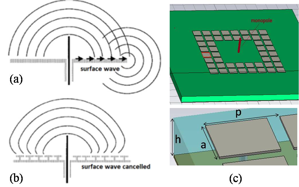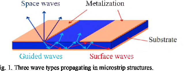

A circular geometry patch antenna may be used to reduce this problem. If active circuitry, which may generate harmonic frequencies, is integrated with the patch antenna, harmonic radiation leading to co-site interference may occur. The problem of electrically thick substrate is also a common one for high-frequency antennas on high-permittivity substrates, and high amounts of TM surface waves can result.īecause the antenna's length determines the resonant frequency of the patch, higher antenna resonances will coincide with frequencies that are multiples of the fundamental resonance. High levels of TM 0 surface waves, however, can result and therefore reduce the radiation efficiency as well as degrade the radiation pattern if the surface wave generates radiation (which can occur at the edge of finite ground antennas). Alternatively, matched bandwidth of the antenna can be increased by making the antenna substrate electrically thicker, effectively lowering the Q-factor of the antenna cavity for increased bandwidth. A review of this technology is discussed in Pozar (1992). Other feed mechanisms have been used to increased bandwidth, including proximity coupling and aperture coupling, both of which require multilayer fabrication. Microstrip-fed patches have very narrow bandwidths, almost invariably less than 5%. Feeding is extremely important with the patch antenna, and it contributes to bandwidth, crosspolarization levels, and ripple. The patch antenna, shown in Figure 11.14 with microstrip feeding, is one of the most widely used planar antennas. In both cases, bandwidth was improved by adding nondriven antenna elements with slightly higher resonant frequencies on the opposite side of the dielectric from the driven element. Reduction of size of the patch and the loop antennas was accompanied by decreased bandwidth. The resonant frequency of the antenna with the metamaterial substrate was reduced somewhat more than what would be expected from the natural pc board substrate alone. 3.12 was used for a patch antenna, where a ground plane larger than the size of the patch was placed at the bottom side of the substrate. A dielectric substrate similar to that shown in Fig.

A greater decrease of resonant frequency was obtained when the split ring resonators were included in the same plane as the loop, both within the loop and outside it, resulting in a size reduction of 38 percent. The resonant frequency with the metamaterial substrate was reduced by 23 percent, which indicates the size reduction. A loop antenna with approximately one wavelength perimeter that resonated in air at 2.58 GHz was mounted over a stack of pc boards on which were etched groups of split ring resonators as shown in Fig. The aim here was to significantly decrease the physical size at the operating frequency. Patch and loop antennas were designed with metamaterial dielectric substrates.


 0 kommentar(er)
